Page 10 - ZSi-Foster Channel Loads
P. 10

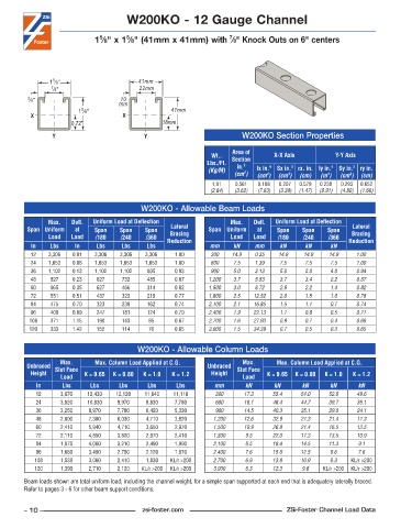
W200KO - 12 Gauge Channel


                                                                     7
                                       5
                               5
                             1 ⁄8" x 1 ⁄8" (41mm x 41mm) with  ⁄8" Knock Outs on 6" centers


                 5
                1 ⁄8"                     41mm
                7 ⁄8"                     22mm
         3 ⁄8"                       10
                                    mm
                         5
                        1 ⁄8"                       41mm
          X                          X
                      0.72"                      18mm
                 Y                          Y                            W200KO Section Properties


                                                                      Area of
                                                                Wt..              X-X Axis           Y-Y Axis
                                                               Lbs./Ft.   Section
                                                                       in.
                                                                         2
                                                               (Kg/M)        lx in. 4   Sx in. 3  rx. in. ly in. 4  Sy in. 3  ry in.
                                                                       (cm )  (cm )  (cm )  (cm)  (m )  (cm )  (cm)
                                                                         2
                                                                                                         3
                                                                                       3
                                                                                4
                                                                                                  4
                                                                1 .91  0 .561  0 .188  0 .207  0 .579  0 .238  0 .293  0 .652
                                                               (2.84)  (3.62)  (7.83)  (3.39)  (1.47)  (9.91)  (4.80)  (1.66)
                                           W200KO - Allowable Beam Loads
               Max.    Defl.   Uniform Load at Deflection             Max.    Defl.   Uniform Load at Deflection
         Span Uniform   at   Span    Span   Span    Lateral    Span Uniform   at   Span    Span   Span    Lateral
               Load   Load   /180    /240   /360    Bracing           Load  Load    /180   /240    /360   Bracing
          In    Lbs    In     Lbs    Lbs     Lbs   Reduction   mm     kN     mm     kN      kN     kN    Reduction
          12   3,306   0 .01  3,306  3,306  3,306    1 .00      300   14.9   0.35   14.9   14.9    14.9    1.00
          24   1,653   0 .06  1,653  1,653  1,653    1 .00      600   7.5    1.39   7.5     7.5    7.5     1.00
          36   1,102   0 .13  1,102  1,102   865     0 .93      900   5.0    3.13   5.0     5.0    4.0     0.94
          48    827    0 .23  827    732     485     0 .87     1,200  3.7    5.53   3.7     3.4    2.2     0.87
          60    665    0 .35  627    466     314     0 .82     1,500  3.0    8.72   2.9     2.2    1.4     0.82
          72    551    0 .51  437    323     219     0 .77     1,800  2.5   12.52   2.0     1.5    1.0     0.78
          84    475    0 .70  323    238     162     0 .74     2,100  2.1   16.85   1.5     1.1    0.7     0.74
          96    409    0 .89  247    181     124     0 .70     2,400  1.9   22.13   1.1     0.8    0.5     0.71
          108   371    1 .15  190    143     95      0 .67     2,700  1.6   27.93   0.9     0.7    0.4     0.68
          120   333    1 .42  152    114     76      0 .65     3,000  1.5   34.39   0.7     0.5    0.3     0.65


                                          W200KO - Allowable Column Loads
                   Max.      Max. Column Load Applied at C.G.            Max.      Max. Column Load Applied at C.G.
         Unbraced  Slot Face                                   Unbraced  Slot Face
          Height          K = 0.65  K = 0.80  K = 1.0  K = 1.2  Height          K = 0.65  K = 0.80  K = 1.0  K = 1.2
                   Load                                                  Load
            In     Lbs      Lbs     Lbs      Lbs     Lbs         mm       kN      kN       kN      kN      kN
            12     3,870   12,430  12,120   11,640   11,110      300      17.3    55.4    54.0     52.0    49.6
            24     3,620   10,830   9,970   8,830    7,780       600     16.1     48.4    44.7     39.7    35.1
            36     3,250   8,970    7,780   6,420    5,330       900     14.5     40.3    35.1     29.0    24.1
            48     2,800   7,300    6,030   4,710    3,820      1,200    12.6     32.9    27.3     21.4    17.3
            60     2,410   5,940    4,710   3,650    2,970      1,500    10.9     26.8    21.4     16.5    13.5
            72     2,110   4,850    3,820   2,970    2,410      1,800     9.5     22.0    17.3     13.5    10.9
            84     1,870   4,060    3,210   2,490    1,990      2,100     8.5     18.4    14.5     11.3    9.1
            96     1,680   3,490    2,760   2,120    1,670      2,400     7.6     15.8    12.5     9.6     7.6
           108     1,530   3,060    2,410   1,830   KL/r >200   2,700     6.9     13.8    10.9     8.3   KL/r >200
           120     1,390   2,710    2,120  KL/r >200  KL/r >200  3,000    6.3     12.3     9.6   KL/r >200  KL/r >200
        Beam loads shown are total uniform load, including the channel weight, for a simple span supported at each end that is adequately laterally braced.
        Refer to pages 3 - 6 for other beam support conditions.


        – 10 –                             zsi-foster.com                             ZSi-Foster Channel Load Data
   5   6   7   8   9   10   11   12   13   14   15