Page 14 - ZSi-Foster Channel Loads
P. 14

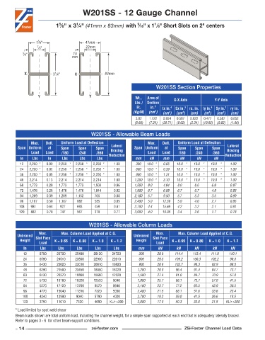
W201SS - 12 Gauge Channel


                            5
                                                                        1
                                    1
                                                                 9
                           1 ⁄8" x 3 ⁄4" (41mm x 83mm) with  ⁄16" x 1 ⁄8" Short Slots on 2" centers
                   5
                  1 ⁄8"                 41mm
                  7 ⁄8"                  22mm
           3 ⁄8"                   10
                                  mm


            X             3 ⁄4"     X            83mm
                          1

                                                                         W201SS Section Properties

                   Y                      Y                     Wt..   Area of   X-X Axis           Y-Y Axis
                                                               Lbs./  Section
                                                                Ft.   in. 2   lx in. 4   Sx in. 3  rx. in.  ly in. 4  Sy in. 3  ry in.
                                                               (Kg/M)  (cm )  (cm )  (cm )  (cm)  (m )  (cm )  (cm)
                                                                         2
                                                                                     3
                                                                               4
                                                                                                 4
                                                                                                        3
                                                                3 .82  1 .122  0 .954  0 .587  0 .922  0 .477  0 .587  0 .652
                                                               (5.68)  (7.24)  (39.71)  (9.62)  (2.34)  (19.85)  (9.62)  (1.66)
                                           W201SS - Allowable Beam Loads
               Max.    Defl.   Uniform Load at Deflection            Max.    Defl.   Uniform Load at Deflection
         Span Uniform   at   Span    Span    Span   Lateral    Span Uniform   at   Span    Span    Span   Lateral
               Load   Load   /180     /240    /360  Bracing          Load   Load    /180   /240    /360   Bracing
          In    Lbs    In     Lbs     Lbs     Lbs  Reduction    mm    kN    mm      kN      kN      kN   Reduction
          12   2,250 *  0 .00  2,250 *  2,250 *  2,250 *  1 .00  300  10.0 *  0.05  10.0 *  10.0 *  10.0 *  1.00
          24   2,250 *  0 .02  2,250 *  2,250 *  2,250 *  1 .00  600  10.0 *  0.39  10.0 *  10.0 *  10.0 *  1.00
          36   2,250 *  0 .05  2,250 *  2,250 *  2,250 *  1 .00  900  10.0 *  1.31  10.0 *  10.0 *  10.0 *  1.00
          48   2,214    0 .13  2,214    2,214    2,214    1 .00  1,200  10.0 *  3.10  10.0 *  10.0 *  10.0 *  1.00
          60   1,773    0 .20  1,773    1,773    1,503    0 .96  1,500  8.0    4.84  8.0     8.0     6.9     0.97
          72   1,476    0 .28  1,476    1,476    1,044    0 .92  1,800  6.7    6.98  6.7     6.7     4.8     0.93
          84   1,269    0 .39  1,269    1,152    765    0 .88  2,100  5.7    9.50  5.7     5.3     3.5     0.89
          96   1,107    0 .50  1,107    882     585    0 .85   2,400  5.0    12.39  5.0     4.0     2.7     0.85
          108  981     0 .64  927     693     459     0 .81    2,700  4.4    15.66  4.2     3.2     2.1     0.81
          120  882     0 .78  747     567     378     0 .77    3,000  4.0    19.36  3.4     2.6     1.7     0.78


                                          W201SS - Allowable Column Loads
                   Max.      Max. Column Load Applied at C.G.            Max.      Max. Column Load Applied at C.G.
         Unbraced  Slot Face                                   Unbraced  Slot Face
          Height          K = 0.65  K = 0.80  K = 1.0  K = 1.2  Height          K = 0.65  K = 0.80  K = 1.0  K = 1.2
                   Load                                                  Load
            In      Lbs     Lbs     Lbs      Lbs      Lbs        mm       kN       kN      kN      kN       kN
            12     6700    25700    25480   25120    24720       300      29.8    114.4   113.4   111.9    110.1
            24     6580    24510    23830   22900    22010       600      29.3    109.2   106.3   102.2    98.3
            36     6430    23020    22010   20810    19820       900      28.6    102.7   98.3     92.9    88.5
            48     6290    21580    20450   18860    16320      1,200     28.0    96.4    91.4     84.7    73.7
            60     6130    20370    18860   15680    12520      1,500     27.4    91.0    84.7     70.9    57.0
            72     5730    19160    16320   12520    9040       1,800     25.7    86.1    73.7     57.0    41.5
            84     5270    17120    13760    9570    6640       2,100     23.7    77.2    62.5     43.9    30.5
            96     4770    15040    11310    7320    5090       2,400     21.5    68.1    51.6     33.6    23.4
           108     4240    12980    9040     5790    4020       2,700     19.2    59.0    41.5     26.6    18.5
           120     3750    11010    7320     4690   KL/r >200   3,000     17.0    50.3    33.6     21.5  KL/r >200
        * Load limited by spot weld shear
        Beam loads shown are total uniform load, including the channel weight, for a simple span supported at each end that is adequately laterally braced.
        Refer to pages 3 - 6  for other beam support conditions.
        – 14 –                             zsi-foster.com                             ZSi-Foster Channel Load Data
   9   10   11   12   13   14   15   16   17   18   19