Page 22 - ZSi-Foster Channel Loads
P. 22

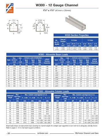
W300 - 12 Gauge Channel


                                                           3
                                                   5
                                                  1 ⁄8" x 1 ⁄8" (41mm x 35mm)


                5
               1 ⁄8"                        41mm
                7 ⁄8"                       22mm
                                      10
         3 ⁄8"                        mm
                        3
         X              1 ⁄8"          X             35mm

                     0.58"                         15mm
                Y                             Y
                                                                           W300 Section Properties
                                                                      Area of
                                                                Wt..   Section    X-X Axis          Y-Y Axis
                                                               Lbs./Ft.   in. 2
                                                               (Kg/M)        lx in. 4   Sx in. 3  rx. in. ly in. 4  Sy in. 3  ry in.
                                                                         2
                                                                      (cm )  (cm )  (cm )  (cm)  (m )  (cm )  (cm)
                                                                                                        3
                                                                                                  4
                                                                                4
                                                                                      3
                                                                1 .73  0 .508  0 .123  0 .158  0 .491  0 .208  0 .256  0 .64
                                                               (2.57)  (3.28)  (5.12)  (2.59)  (1.25)  (8.66)  (4.20)  (1.63)
                                             W300 - Allowable Beam Loads
               Max.    Defl.   Uniform Load at Deflection             Max.    Defl.   Uniform Load at Deflection
         Span Uniform   at   Span    Span   Span    Lateral    Span Uniform   at   Span    Span   Span    Lateral
               Load   Load   /180    /240   /360    Bracing           Load  Load    /180   /240    /360   Bracing
          In    Lbs    In     Lbs    Lbs     Lbs   Reduction   mm     kN     mm     kN      kN     kN    Reduction
          12   2,650   0 .02  2,650  2,650  2,650    1 .00      300   12.0   0.40   12.0   12.0    12.0    1.00
          24   1,320   0 .07  1,320  1,320  1,320    1 .00      600   6.0    1.63   6.0     6.0    6.0     1.00
          36    880    0 .15  880    880     600     0 .96      900   4.0    3.66   4.0     4.0    2.8     0.96
          48    660    0 .26  660    500     340     0 .91     1,200  3.0    6.46   3.0     2.3    1.6     0.91
          60    530    0 .41  430    320     210     0 .87     1,500  2.4   10.16   2.0     1.5    1.0     0.87
          72    440    0 .59  300    220     150     0 .84     1,800  2.0   14.63   1.4     1.0    0.7     0.84
          84    380    0 .81  220    160     110     0 .81     2,100  1.7   19.62   1.0     0.8    0.5     0.81
          96    330    1 .05  170    130     80      0 .78     2,400  1.5   26.21   0.8     0.6    0.4     0.79
          108   290    1 .31  130    100     70      0 .76     2,700  1.3   32.92   0.6     0.4    0.3     0.76
          120   260    1 .62  110     80     50      0 .74     3,000  1.2   40.65   0.5     0.4    0.3     0.74


                                            W300 - Allowable Column Loads
                   Max.      Max. Column Load Applied at C.G.            Max.      Max. Column Load Applied at C.G.
         Unbraced  Slot Face                                   Unbraced  Slot Face
          Height          K = 0.65  K = 0.80  K = 1.0  K = 1.2  Height          K = 0.65  K = 0.80  K = 1.0  K = 1.2
                   Load                                                  Load
            In     Lbs      Lbs     Lbs      Lbs     Lbs         mm       kN      kN       kN      kN      kN
            12     3480    11260    10980   10550    10080       300      15.5    50.1    48.9     47.1    45.0
            24     3260     9830    9100     8150    7280        600     14.5     43.9    40.7     36.6    32.7
            36     2980     8260    7280     6180    5280        900     13.3     37.1    32.7     27.8    23.8
            48     2640     6890    5860     4760    3890       1,200    11.8     31.0    26.4     21.5    17.6
            60     2340     5780    4760     3720    3010       1,500    10.5     26.1    21.5     16.8    13.7
            72     2080     4880    3890     3010    2330       1,800     9.3     22.1    17.6     13.7    10.7
            84     1860     4130    3270     2470   KL/r >200   2,100     8.4     18.7    14.8     11.3  KL/r >200
            96     1680     3550    2790     1890   KL/r >200   2,400     7.6     16.1    12.6     8.7   KL/r >200
           108     1480     3110    2330   KL/r >200  KL/r >200  2,700    6.8     14.1    10.7   KL/r >200  KL/r >200
           120     1280     2740    1890   KL/r >200  KL/r >200  3,000    5.8     12.4     8.7   KL/r >200  KL/r >200
        Beam loads shown are total uniform load, including the channel weight, for a simple span supported at each end that is adequately laterally braced.
        Refer to pages 3 - 6 for other beam support conditions.


        – 22 –                             zsi-foster.com                             ZSi-Foster Channel Load Data
   17   18   19   20   21   22   23   24   25   26   27