Page 25 - ZSi-Foster Channel Loads
P. 25

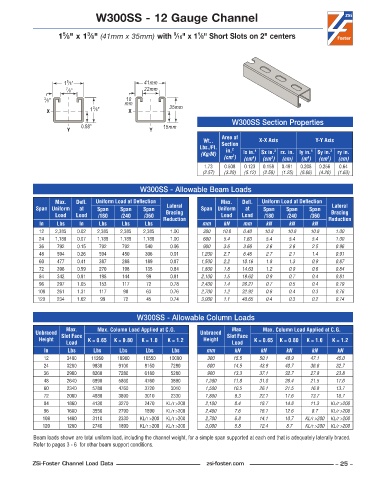
W300SS - 12 Gauge Channel


                                                          9
                                                                  1
                              3
                      5
                    1 ⁄8" x 1 ⁄8" (41mm x 35mm) with  ⁄16" x 1 ⁄8" Short Slots on 2" centers


                       5
                      1 ⁄8"                     41mm
                       7 ⁄8"                    22mm
                                          10
               3 ⁄8"                      mm
                               3
                X             1 ⁄8"        X            35mm
                                                                             W300SS Section Properties
                            0.58"                     15mm
                       Y                          Y
                                                                         Area of
                                                                   Wt..   Section     X-X Axis          Y-Y Axis
                                                                  Lbs./Ft.   in. 2
                                                                   (Kg/M)       lx in. 4   Sx in. 3  rx. in. ly in. 4  Sy in. 3  ry in.
                                                                          (cm )  (cm )  (cm )  (cm)  (m )  (cm )  (cm)
                                                                             2
                                                                                                            3
                                                                                   4
                                                                                          3
                                                                                                     4
                                                                    1 .73  0 .508  0 .123  0 .158  0 .491  0 .208  0 .256  0 .64
                                                                   (2.57)  (3.28)  (5.12)  (2.59)  (1.25)  (8.66)  (4.20)  (1.63)
                                               W300SS - Allowable Beam Loads
                   Max.    Defl.   Uniform Load at Deflection            Max.    Defl.   Uniform Load at Deflection
             Span Uniform   at   Span   Span    Span   Lateral     Span Uniform   at   Span   Span    Span   Lateral
                   Load   Load   /180    /240   /360   Bracing           Load   Load   /180    /240   /360   Bracing
              In    Lbs    In    Lbs     Lbs    Lbs   Reduction    mm     kN    mm      kN     kN      kN   Reduction
              12   2,385  0 .02  2,385  2,385   2,385    1 .00     300    10.8  0.40   10.8    10.8   10.8     1.00
              24   1,188  0 .07  1,188  1,188   1,188    1 .00     600    5.4   1.63    5.4    5.4     5.4     1.00
              36    792   0 .15  792     792    540      0 .96     900    3.6   3.66    3.6    3.6     2.5     0.96
              48    594   0 .26  594     450    306      0 .91     1,200  2.7   6.46    2.7    2.1     1.4     0.91
              60    477   0 .41  387     288    189      0 .87     1,500  2.2   10.16   1.8    1.3     0.9     0.87
              72    396   0 .59  270     198    135      0 .84     1,800  1.8   14.63   1.2    0.9     0.6     0.84
              84    342   0 .81  198     144     99      0 .81     2,100  1.5   19.62   0.9    0.7     0.4     0.81
              96    297   1 .05  153     117     72      0 .78     2,400  1.4   26.21   0.7    0.5     0.4     0.79
             108    261   1 .31  117     90      63      0 .76     2,700  1.2   32.92   0.6    0.4     0.3     0.76
             120    234   1 .62   99     72      45      0 .74     3,000  1.1   40.65   0.4    0.3     0.2     0.74


                                              W300SS - Allowable Column Loads
                       Max.      Max. Column Load Applied at C.G.            Max.      Max. Column Load Applied at C.G.
             Unbraced  Slot Face                                  Unbraced  Slot Face
              Height          K = 0.65  K = 0.80  K = 1.0  K = 1.2  Height          K = 0.65  K = 0.80  K = 1.0  K = 1.2
                       Load                                                  Load
               In      Lbs      Lbs     Lbs      Lbs     Lbs        mm        kN      kN      kN       kN      kN
               12      3480    11260   10980    10550   10080        300     15.5     50.1    48.9    47.1     45.0
               24      3260    9830     9100    8150     7280        600     14.5     43.9    40.7    36.6     32.7
               36      2980    8260     7280    6180     5280        900     13.3     37.1    32.7    27.8     23.8
               48      2640    6890     5860    4760     3890       1,200    11.8     31.0    26.4    21.5     17.6
               60      2340    5780     4760    3720     3010       1,500    10.5     26.1    21.5    16.8     13.7
               72      2080    4880     3890    3010     2330       1,800     9.3     22.1    17.6    13.7     10.7
               84      1860    4130     3270    2470   KL/r >200    2,100     8.4     18.7    14.8    11.3   KL/r >200
               96      1680    3550     2790    1890   KL/r >200    2,400     7.6     16.1    12.6     8.7   KL/r >200
               108     1480    3110     2330   KL/r >200  KL/r >200  2,700    6.8     14.1    10.7   KL/r >200  KL/r >200
               120     1280    2740     1890   KL/r >200  KL/r >200  3,000    5.8     12.4    8.7    KL/r >200  KL/r >200
            Beam loads shown are total uniform load, including the channel weight, for a simple span supported at each end that is adequately laterally braced.
            Refer to pages 3 - 6  for other beam support conditions.


            ZSi-Foster Channel Load Data                            zsi-foster.com                             – 25 –
   20   21   22   23   24   25   26   27   28   29   30